Nordic Fob Revival
by Jared Julien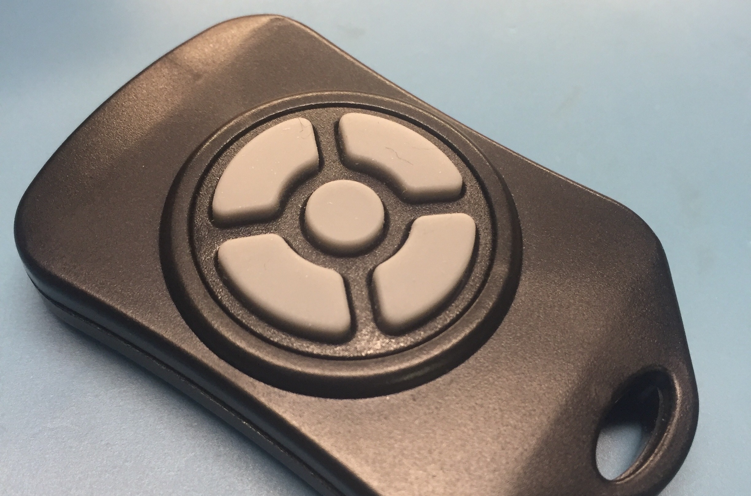
Several years back SparkFun made a really cool product that they referred to as the Nordic FOB. The product is now “retired” (i.e. not for sale) but the schematics are still fully available for download along with the source code so I decided to resurrect the device and build some myself. SparkFun doesn’t offer any direct replacements for the fob despite that they still carry a number of development boards using the same SoC that was used in the fob. While there are no specific indications regarding the premature retirement of a beloved product it is my belief that it has ties to FCC regulations. SparkFun themselves have posted a lovely primer regarding the FCC and open source hardware and what it takes to create and license an “intentional radiator”, which is FCC speak for any device that knowingly transmits RF data. I believe that there is a thin line between a product that they sell that enables someone else to create an “intentional radiator” (like a development board) and a product that is itself considered one. The fob, unfortunately, would fall under the later category and as such would require testing and subsequent FCC licensing to be sold. All of that means that they cannot legally sell the device without pouring a ton of cash into the proper certification (which would likely not be profitable given the limited quantities of the devices that they would sell). However, nothing stops them from giving away the plans for someone else to make their own and that’s exactly what I did.
Disclaimer: I have no idea if my above assumptions are correct. SparkFun is a great company and I don’t mean for any of my comments to come across as a slight to them in any way.
I began with their design for the fob and made some tweaks to make it a bit easier to construct by hand, namely upping the passives components from 0402 to 0603 parts. I retained the same case which is still available directly from PolyCase (bonus: they offer different button combinations all of which work with this design). The following log details the design and the changes that I made to it. If like me you want to get your hands on one of these fobs then I encourage you to take my files, order the parts and PCBs and dust off your soldering iron. Don’t let surface mount parts scare you, they’re relatively easy to solder by hand. All you need is a good pair of tweezers and some patience. A quality soldering iron with a small tip and some very thin solder help but are not absolutely required. Some day I may write up a tutorial of sorts on hand soldering surface mount parts just to show how simple it really is.
Basis
This entire project is based upon a retired product from SparkFun . They still host the Eagle files for the PCB as well as the source code for the ATmega24 on board. Just in case those should ever disappear, here’s a mirror of them:
Overview
The fob is nothing more than a small remote with up to five buttons on it that, when pressed, wake up a micro controller and transmits the event over an RF channel. The receiver is outside the scope of this project and can be anything that needs to be controlled from a PC to a blinky Christmas light controller.
Under the hood, an ATmega24 handles the button presses and communication with an NRF24L01+ SoC from Nordic Semiconductor (hence the name, Nordic fob (please don’t sue me, I’m not claiming any rights to the title)). When a button is pressed, the micro will wake from low power mode, pull the radio out of sleep, transmit the button press along with a rolling counter, put the radio back to sleep, and return to low power mode to conserve battery life.
Beyond the basics the fob contains a slew of passive components required to make the radio function which are pretty much based upon the reference design from Nordic directly out of the NRF24L01+ datasheet . Here’s a picture of the inside of the FOB with a detailed view of the PCB and all of the components.
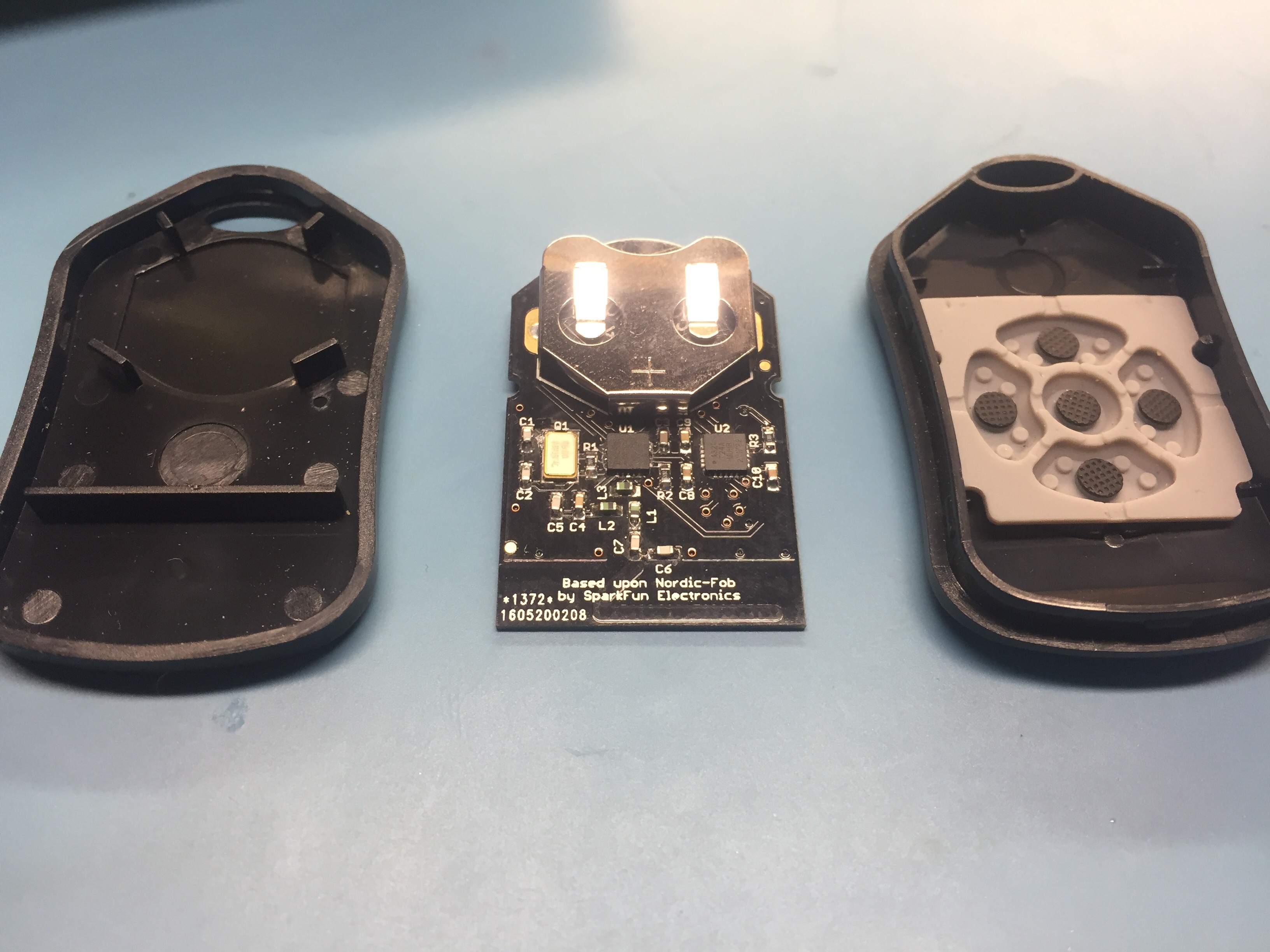
The big silver blob at the top holds a CR2025 lithium battery which fits perfectly between the little plastic nubs in the bottom of the case. The smaller silver blob on the left is a 16MHz crystal for the radio which is the black blob in the center and the ATMega24 is located off to the right. The space along the bottom lacking components and adorned with lovely white text serves as a PCB trace antenna for the radio. I do not claim to be any sort of electromagnetic expert of any sort (I barely passed my E-mag courses) so I took the antenna design, verbatim, from the original SparkFun design. It seems to work satisfactory for my use cases at least even though PCB antennas are considered somewhat inferior (or so I have been told).
Case
The case is part of the FB-20 series from PolyCase. They make versions ranging from a single button up to the five button model pictured above. Any of the models will work with this project without any modifications to the PCB or firmware.
- 1 Button: FB-20-1
- 2 Button: FB-20-2
- 3 Button: FB-20-3
- 4 Button: FB-20-4
- 5 Button: FB-20-5
Hardware
I redesigned the original PCB to swap out the 0402 parts for 0603. While I don’t have any trouble withing with the small 0603 parts by hand I do find 0402 to be a tad tricky. Given that space is not a major problem with this project I decided to up the size of the parts. This required some minor shifting of some components to make enough room for the larger components.
If you’re looking to make one of these fobs, you can find the BOM, schematic, Eagle files, and gerbers all below. The best option for the PCBs is to go with a service such as Dirty PCBs and opt for the 0.8mm thickness boards. The thinner boards will fit inside the case without modification. I originally ordered some pretty purple PCBs from OSHPark but they don’t offer any options and come in a pretty standard thickness. While I would ordinarily prefer the thicker PCBs as they are much more sturdy they are difficult to squeeze into the fob case and ultimately require some of the plastic to be shaved down to make it fit. When ordering you can just upload the gerbers zip active from below and select your favorite color. In a few weeks the boards will arrive and the soldering fun begins.
Admittedly the passives are easy to solder by hand but the two QFN ICs prove to be tricky. This is where having a little patience helps. Simply tack one pin and once your happy with the centering, work you way around the IC just like any other surface mount IC. There isn’t much of each pin that’s exposed but there is enough to be able to get good contact. I’ve soldered all of mine by hand and only exchanged a few choice words with my soldering iron.
- RfRemoteFob_0200_Schematic
- RfRemoteFob_0200_Gerbers
- RfRemoteFob_0200_BOM
- RfRemoteFob_0200_EagleFiles
Software
The software from the fob is very simplistic. As mentioned above, the software puts the micro and radio into low-power mode until a button is pressed. Upon pressing a button the micro controller is woken up which in turn enables the radio. The controller then sends a packet indicating which button or buttons have been pressed along with a rolling counter. The micro then disables the radio and goes back to sleep to conserve power.
This design doesn’t have any sort of fancy-pants bootloader or nifty USB connections. A programmer such as the AVR Dragon or the AVRISP2 is required to program the ATmega24 in circuit after the hardware is assembled. My personal go-to is the AVRISP2 and the ISP header on the PCB is known to work with that programmer. Ideally, a pogo pin jig would be used to make contact with the pads on the PCB. If you don’t have something that fancy lying around then a 2x3 male header pressed manually against the contacts should suffice. You could also solder the header onto the PCB surface mount style until programming is complete and then desolder the header before installation into the case. The later method is probably the most reliable but is also the most time consuming.
The code below was developed on Windowz using WinAVR.
Disclaimer
I have built and tested several of these fobs at home and am very happy with their operation. Before seriously considering building more than a couple of these for yourself (moreover if you’re considering selling these things) you should consider reading this article.
TL;DR: if you’re in the United States, you can make up to 5 devices as a hobbyist to keep for yourself before anyone will care. If you wish to make more, or if you want to give them away or sell them then you will need to have a conversation with the FCC. They will want you to pursue a lengthy regimen of tests and certifications for the product which will cost you a considerable sum of money. If you’re not in the US, the laws will be different but will most likely be similar as every country has some form of regulatory commission governing their airwaves. Because this is a packaged device and it’s an “intentional radiator” (meaning simply that it knowingly puts out RF waves) it must be certified. Long story short, please be responsible for you own actions and know what you’re doing.
Disclaimer to the disclaimer: I’m not a lawyer, do your own research. The FCC makes all of their regulations publicly available. You’ll need to sift though the leagaleze yourself to figure out if what you want to do is within the bounds of that which they allow.
Sorry I’m a buzz kill. Leave a comment below if you’ve got any questions about this project or if you managed to make a Nordic fob of your own then I would love to hear about it. Happy making!