Reverse Geocache Puzzle
by Jared Julien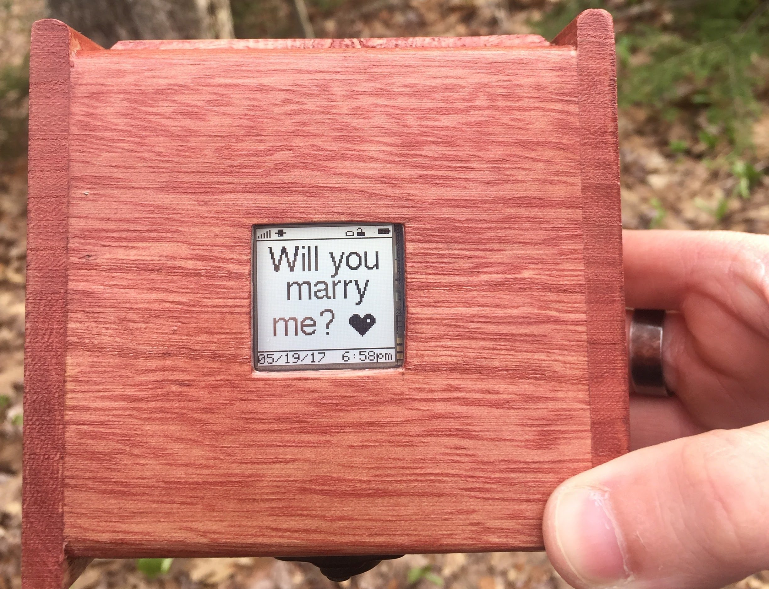


The reverse geocache puzzle was made famous by Mikal Hart. I saw his design in Make Volume 25 some time ago and decided that I was going to eventually build one of these devices. The box contains a mechanical latch mechanism that holds it closed and a GPS module to know it’s current location. The latch will only be released when the box is carried to a specific, predetermined location.
Overview
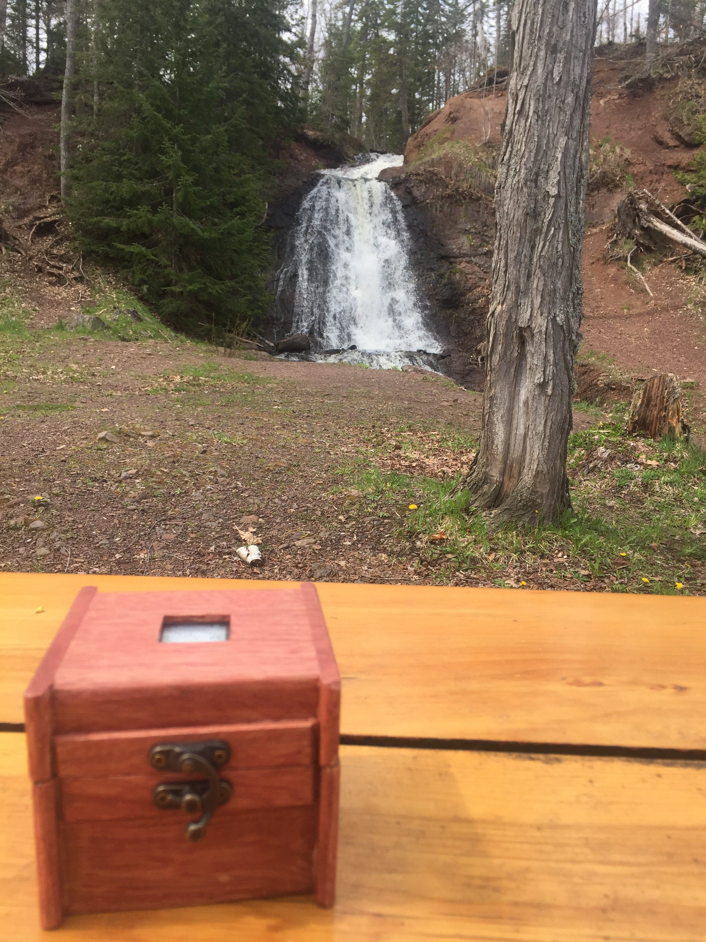
In a similar fashion to the many others that have cloned Mikal Hart’s Reverse Geocache puzzle idea, I built it to propose to my girlfriend. We enjoy being outdoors and exploring new areas and while I was away at college we found a couple of neat places in the upper peninsula of Michigan that became quite special. When we decided to take a vacation to the area I knew that the time was right to propose to her and this project became a reality. I took the awesome idea from Mikal and polished it a bit for my needs to create a version that I was happy with.
Hardware Differences
I took a slightly different approach for the electronics hardware. Rather than purchase modules from the usual sources such as Adafruit and Sparkfun I decided to design a PCB specifically for this purpose. I did this primarily to get all of the features that I wanted while saving space in the relatively small enclosure. Don’t be deterred by this if you want to attempt the project. The PCB designs are open source and you can send the Gerber files to any board house such as Dirty PCBs or OSHPark and the components are freely available from Mouser, Adafruit, and Sparkfun. Some of the ICs are a little tricky to solder by hand, but I didn’t use any special tools to put mine together, just a decent soldering iron, some tweezers, and some patience.
In a nutshell, the PCB contains nothing more than the equivalent of an Arduino Pro Mini (3.3V, 8MHz), an Adafruit Ultimate GPS module, an Adafruit 5V Buck/Boost converter, a SparkFun LiPower shield, and an FTDI breakout. In theory, the same device could be assembled using these modules individually. And this is the reason that open source hardware rocks! I was able to use each of these designs freely in my project which a great deal of confidence that they would work as expected with minimal debugging, but I digress… I also threw in the circuit for the Wake-on-Shake module from SparkFun with the idea that it could be used to detect when the module was being carried but I never fleshed that idea out and it really wasn’t required for operation.
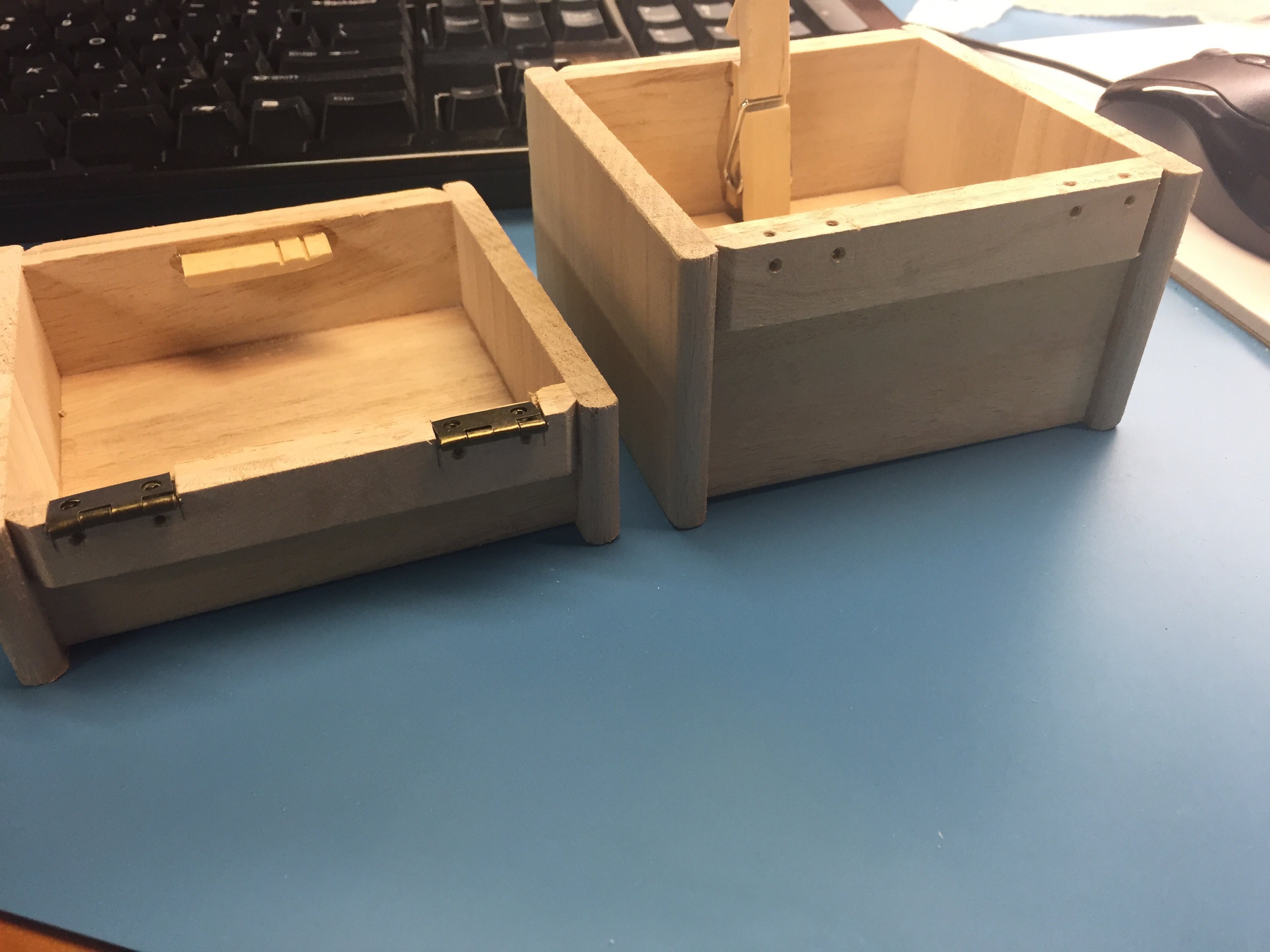
Regarding the box, I have used a small basswood box that I purchased from Michael’s to house my project but really any box will do. You may need to get crafty with the latching mechanism but ideally the box should have hinges just to make the latch a bit easier. My original idea was to use an old cigar box that I had laying around but I liked the smaller size and ability to apply my own finish afforded by the box from Michael’s.
The display that I selected from the project is a Sharp “Memory” display. I liked that it was incredibly low power and was daylight-readable. I was mistaken in my original assumption that “memory” meant that it would retain it’s image when power is removed. Fortunately I made a design error in the hardware that doesn’t allow the display to be shut off anyways. Err, uh… feature - that’s it! But without a backlight this little display is quoted to only consume something like 40uA!
Rather than use AA batteries as Mikal did in his design I opted to use a LiPo I had picked up from SparkFun some time ago. The battery is 2000mAh which without even doing the math translates to a TON of run time for this device. I also baked into the hardware a LiPo charger circuit and a fuel gauge based upon SparkFun’s design for their LiPower Arduino shield. The battery is charged via a USB mini-B connection that protrudes slightly from the side of the enclosure. The device can also be used at the same time it is being charged so that I can keep it plugged into a USB charge adapter in the vehicle while traveling to the destination(s).
Speaking of the USB connection, the USB connector doubles as an access point for communication and reprogramming* in addition to it’s ability to charging the battery. Inside is the same circuitry as on an early Arduino (before they moved away from FTDI).
*See the section below about security to understand how the reprogramming works.
A capacitive touch sensor from Adafruit was used as an input device. The module is fairly low current when in standby but afforded me not to have to cut another hole in my box. The sensor is able to calibrate the wooden box away and reliably detect the presence of a finger on the other side.
For the latch mechanism I made use of a modified clothes pin glued to the inside of the box an a micro hobby servo to “push” the clothes pin to unlock the box. Essentially the box is locked by default using the spring in the clothes pin to mechanically hold it in a locked position and when the time comes to open the box the servo presses the clothes pin back to release the latch. The servo operates off 5 volts while the remainder of the circuit uses 3.3V which meant that I needed a boost converter to generate the 5V. Fortunately Adafruit has a reference design for just such a thing that I was able to crib from and even tie the enable line back to the micro controller. That allows me to disable the converter and the servo when the latch is not moving (99% of the time) to conserve power significantly.
Software Differences
I opted for semi-continuous and unlimited updates for my puzzle. Mikal’s design would sleep until the user pressed a button, report a distance, and then go back to sleep. These attempts were limited to a finite number which might be fun under the right circumstances, but in my case that was not an aspect that I desired. I wanted my better half to eventually find the destination no matter what. My version simply puts the peripherals and micro controller to sleep for 8 seconds or until woken via a touch sensor “button” press at which point it will print the current distance to the destination and go back to sleep.
In the sleep mode the device turns off the GPS, servo, and boost converter while stopping updates to the display and it holds the external RAM and accelerometer (if populated) in a low power state all to keep power consumption to an absolute minimum.
I decided that if it was fun to have a single destination that it must be more fun to have even more destinations! My version of the puzzle contains a series of way-points that must be found before the box will unlock at it’s final destination. These way-points are predetermined by me and were designed to take us on a journey to our favorite spots before finally turning up at a special location to pop the big question.
While she is certainly not a hacker at heart I did take security into account for this puzzle. I installed a normally open tamper switch that would detect if the box was opened before being unlocked and in the software this state is stored to EEPROM and retained (along with a big message on the display) until it is manually reset via software. This would hopefully guard against prying the device open (or at least deter - I suppose this isn’t really a “security” feature). Also, reprogramming is disabled via a jumper setting on the PCB such that the device cannot be reprogrammed after it’s setup and locked preventing someone from flashing special software to operate the latch.
The commands to lock and unlock the box are given via USB/serial connection and require a pass code value that it stored in EEPROM when the box is locked. The matching pass code must be supplied with the unlock command to successfully unlock the box and it even guards against brute force attacks by enforcing a time delay between unlock requests. This provides a back door similar to Mikal’s but adds some security to that.
Summary
As an engineer, I always strive to build the better mousetrap - even when the need doesn’t exist. I would like to thank Mikal for the idea of such a puzzle as I likely would have never come up with it on my own. I have made a number of changes to the design to better suit my needs but by no means is this the only way to build a reverse geocache. Please take my design and ideas and leverage them as I have done to build an even better version of this project. I urge you to share what you come up with.
Parts List
- 1 x Enclosure: I used a wooden box purchased from Michaels, but an old cigar box would work just as well. It just needs to be somewhat secure and easily modified for an internal latching mechanism.
- 1 x Micro Servo: Any servo will do fine but smaller is better if you have a small box.
- 1 x Sharp Memory Display: This display has a very low current consumption which is great for battery powered projects.
- 1 x GPS Module: Any GPS module should do. The referenced one from Adafruit is just nicely supported and easy to use.
- 1 x Momentary Touch Sensor: Not strictly required as the current software never goes to sleep so this button is not needed. The referenced sensor does, in fact, work through the wooden box lid though.
- 1 x LiPo Battery: Should be modestly large in terms of capacity but any single cell LiPo with a JST connector will work. The larger the capacity the longer the box will last between charges. The 2000mAh gives about 72 continuous hours of operation (which is far more than I had anticipated).
- 1 x PCB: This item is custom but all of the design files are available if you want to make one yourself. See the assembly instructions below for more information.
Hardware Construction
The steps below detail the build process for the puzzle box hardware.
Step 1: Box Prep
Start with the box - it will need to be modified to support an internal latching mechanism. The goal is for the box to be somewhat secure such that it cannot be easily opened. Obviously there are ways to compromise the integrity of a wooden box so if real security is a concern then go with a metal box instead.
For the box that I used, the first thing that I did was to move the hinges from the back to the inside of the box so that they could not be unscrewed without opening the box. This required some handy work with an Exacto knife and an emery board which was easy with the soft basswood box.
Step 2: The Latch
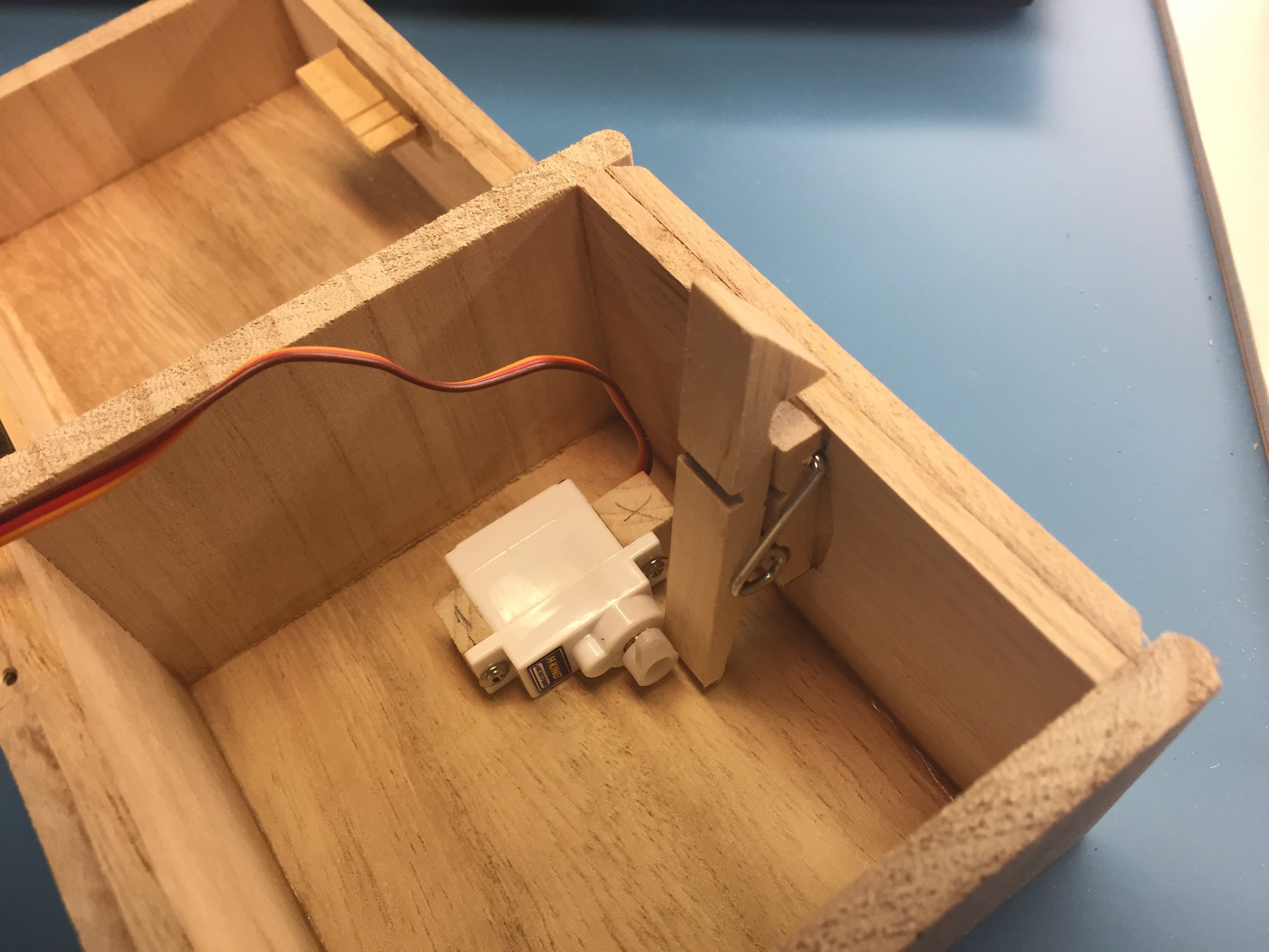
Next, devise a latch mechanism for the box. For mine, I used a modified clothes pin where I glued on a triangular portion of wood at the top and sanded it smooth to make a “tooth” that could catch a strip of wood glued to the lid. I cut down the other side of the clothes pin and glued it to the enclosure retaining the original spring mechanism. The spring holds the latch mechanism together and holds it in the locked position.
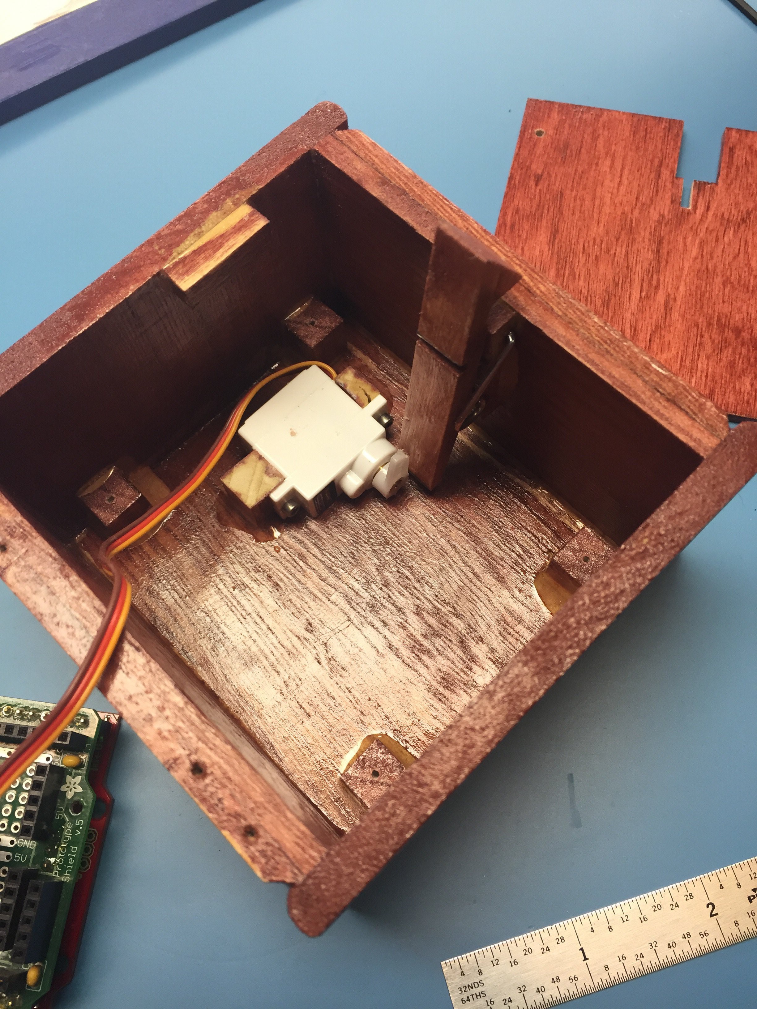
I then used a small hobby servo to push the bottom of the clothes pin forward to unlock the box when desired. Below is a detail shot showing the latch in the “locked” position:
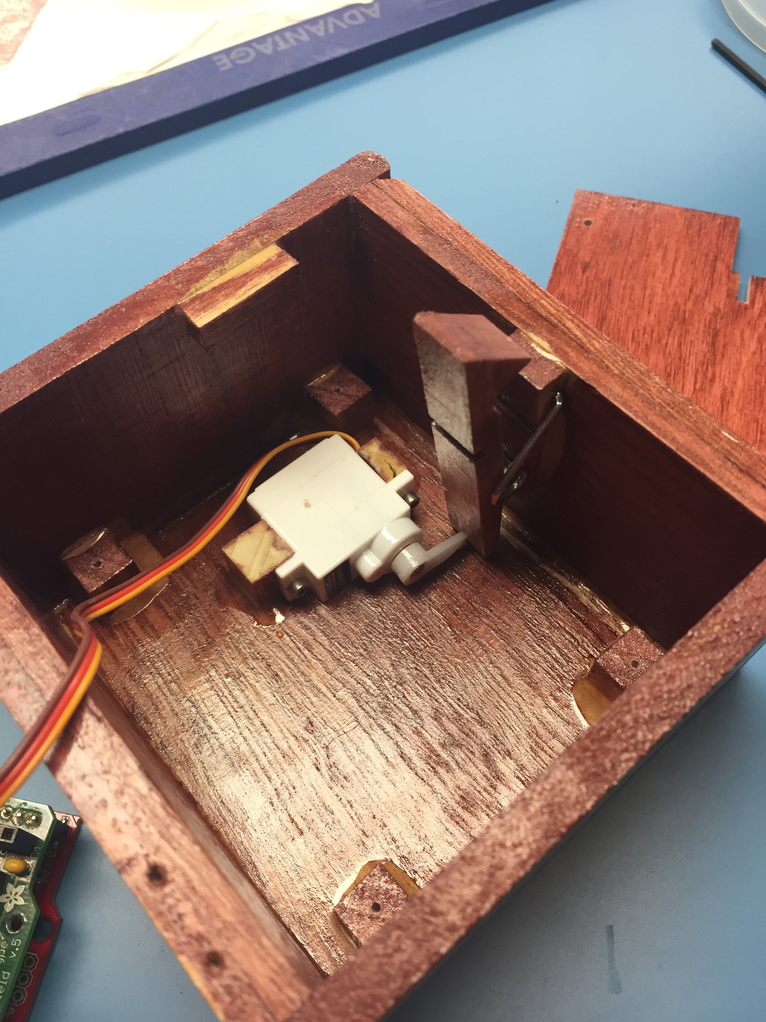
And another below showing the unlocked position:
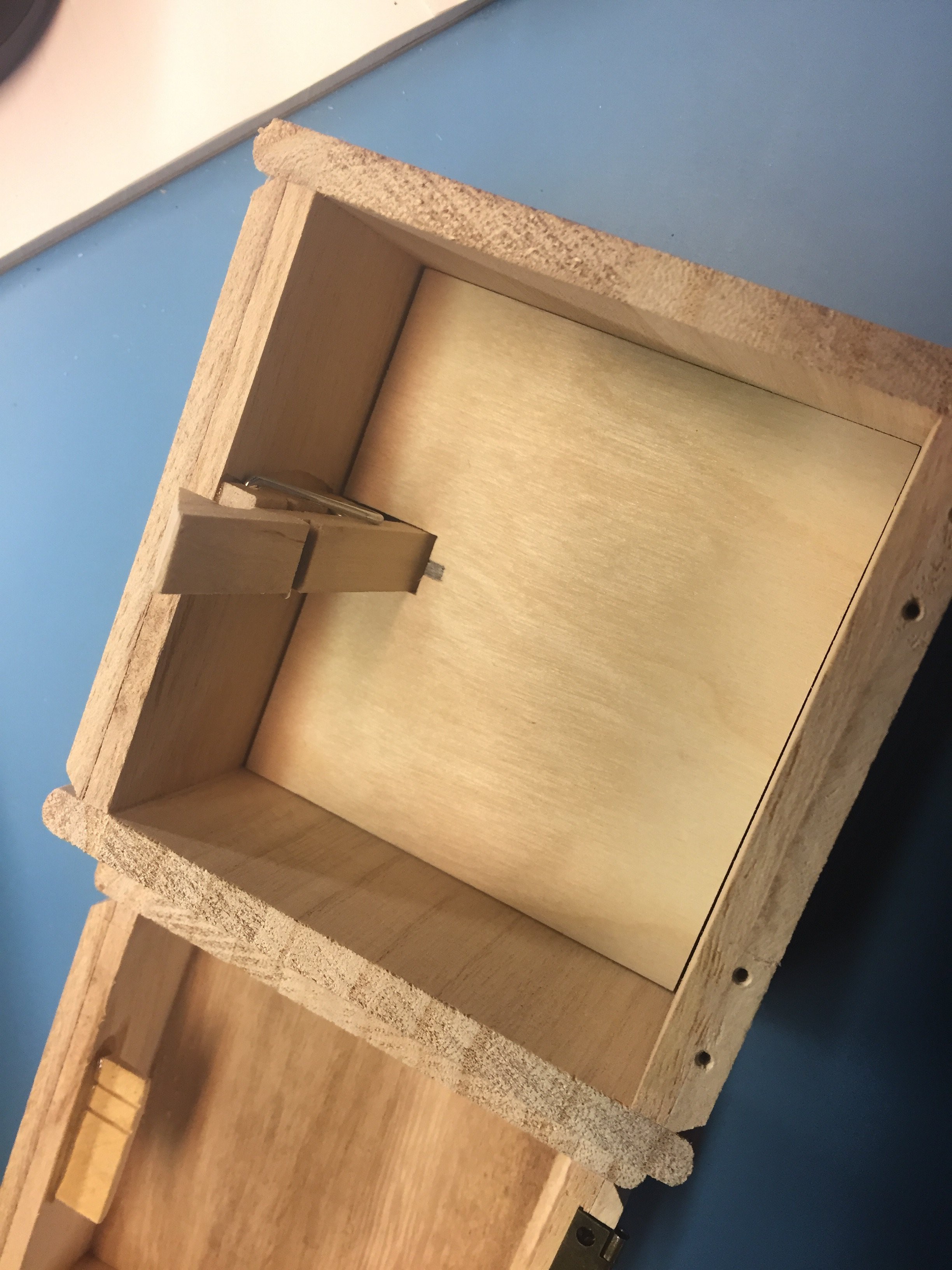
To keep the bottom of the box clean I then covered the servo with a false bottom made out of a thin piece of aircraft plywood.
Step 3: Mount Peripheral Devices

Mount the LCD screen and momentary touch sensor to the lid of the box. This part isn’t too complicated, basically just cut a hole the size of the screen in the lid and mount the LCD behind it. I ended up using a couple of Popsicle sticks glued to the back of the lid as standoffs for the LCD just to get a snug fit.
The picture shows the hole in the lid and the “standoffs” for the LCD. The mounting ears for the Adafruit display breakout board attach to the four holes through the Popsicle sicks on either side of the hole.
What’s not as obvious is the mounting location for the touch sensor. The location for the sensor is not critical. It just needs to be mounted flat on the backside of the lid. The sensor itself will self-calibrate to account for the wood to be able to properly detect a finger on the opposite side. I’m not sure the limitations of this sensor, but I am having great success using it through this ~1/4” thickness basswood box.
This is also a good time to mount the tamper switch which is also pictured above. This simple level switch is held in the closed position by the small wooden tab glued to the bottom half of the box, seen in the picture above as the poorly stained bit in the lower side. This switch is used to detect when the box is opened without being unlocked.
Step 4: Build The PCB

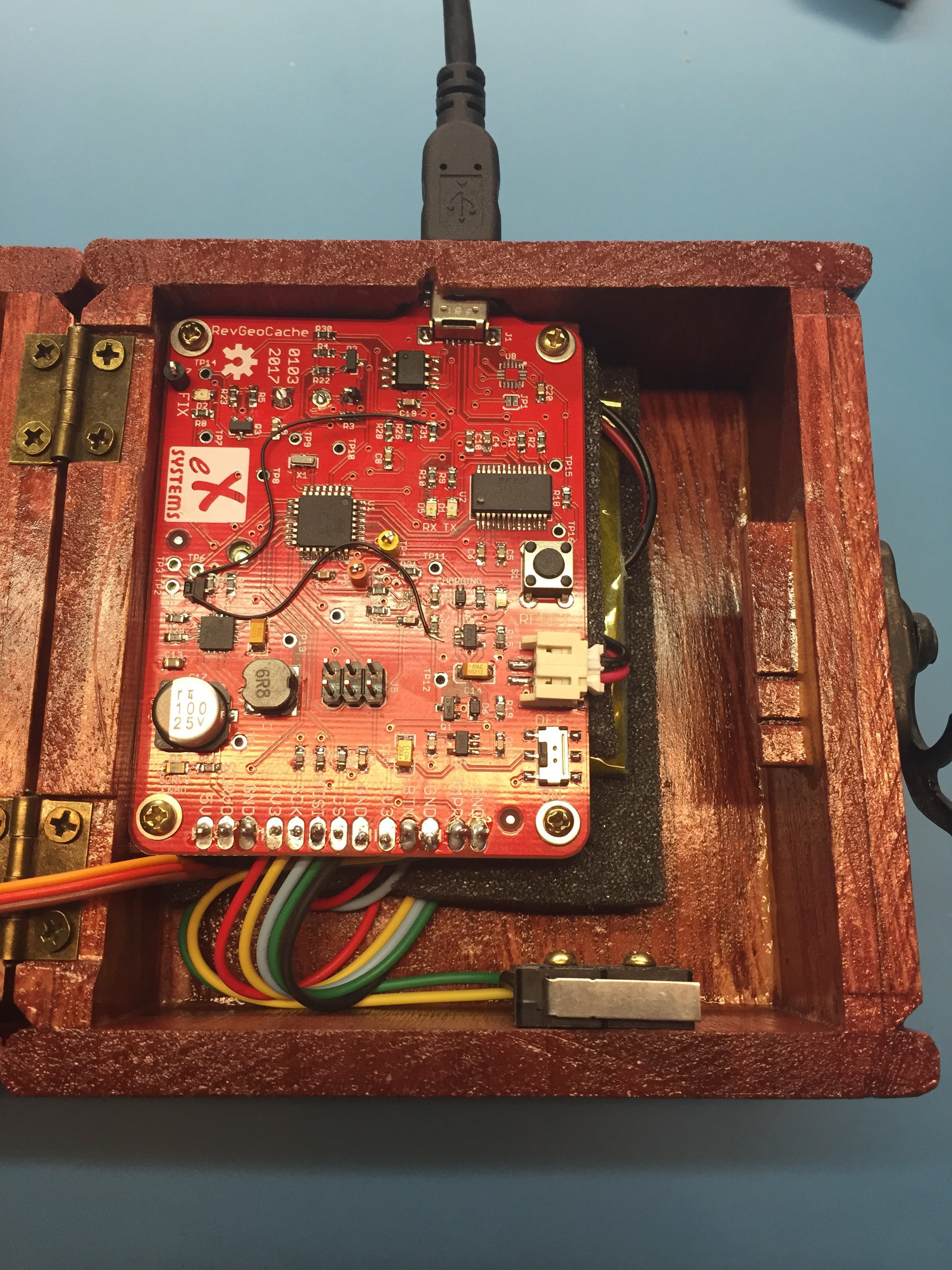
This is a big step and I don’t plan to put a lot of detail here. You will need to get the PCBs fabricated (either DIY or through a board house such as DirtyPCBs or OSHpark), order parts (from Adafruit, SparkFun, and Mouser if you follow my BOM to a ‘T’), and assemble the boards according to the schematic.
One important note is that the board pictured above is an older version of hardware which had some bugs. This picture shows the board just after assembly but some of the other photos show some hardware modifications including some fly wires between points on the board. Don’t worry about those, the issues have been corrected in version 1.5 of the hardware and those modifications are not necessary.
Don’t be discouraged by this portion of the project. The parts are small but I don’t use any overly specialized tools to assemble my PCBs - just a pair of tweezers, some really fine solder, the finest tip I can find for a quality soldering iron, and a lot of patience.
One thing I can’t stress enough is alignment on the fine pitched ICs. Start by aligning the IC and tacking a single pin to the board. Before proceeding check the alignment of all of the pins. If any are off, carefully reheat the tacked pin and adjust the alignment of the device. Repeat until all of the pins are sitting squarely on top of their pads and then proceed with soldering the remaining pins. This will ensure a quality connection for each pin and reduce solder bridges between them.
I don’t want this to be a soldering tutorial, there are already plenty of those out there. Check out Adafruit or SparkFun or even Google and the rest of the internet if you’re new to this. If you have any questions please leave a comment and I’ll do my best to offer help. And if there’s enough interest I can possibly put together a separate tutorial for PCB assembly.
Hardware files:
- RevGeoCache_0105_Schematic
- RevGeoCache_0105_BOM
- RevGeoCache_0105_EagleFiles
- RevGeoCache_0105_Gerbers
Step 5: Mount the PCB
I built some standoffs with some square dowel rods that are to be used to secure the 4 corners of the PCB to the backside of the box lid. I intentionally made the PCB sit high above the LCD to give enough room to sandwich the LiPo battery between a couple sheets of open cell foam rubber below it. This became the battery mount then too.
The last step needed before mounting the PCB is to clear a hole for the USB connector to exit through. The PCB is designed such that the USB connector extends out far enough to exit the side of the box that I used. Before making everything final ensure that you are able to securely plug a USB cable into the connector.
Software
First of all, you will need to put a bootloader on the part. The easiest method is to connect an AVRISP2, or equivalent, to the ISP header, power the PCB over the USB connection, and use the Arduino IDE to “Burn Bootloader” after selecting Arduino Pro Mini (3.3V, 8MHz) from the devices list.
Once that’s complete, you can upload code using PlatformIO. If code in the repository includes several libraries which PlatformIO should fetch and install. Once compilation is complete it will upload over the USB connection to the AVR. Ensure that the jumper adjacent to the reset button is set to the ENA position to allow the FDTI interface to reset the AVR - without that programming will fail.
You will need to adjust the list of destinations in Position.cpp to one or more destinations of your choosing. If you use Google Maps you can single click at any location on the map and copy the coordinates. There seems to be enough accuracy in Google Maps as well as with the GPS to ensure accuracy within the +/- 20 meter tolerance, YMMV.
After re-flashing with your destinations loaded you need to “arm” the box. To do this, leave the USB cable connected to your computer, open a serial terminal and connect at 19200 baud, 8N1 (if you don’t know what that means then the default is probably okay). Then type the following “start xxxx” but replace the “xxxx” with a pass code of your choosing. This will be needed if you elect to issue the “unlock” command at a later time. The box should lock and reset to destination one.
The LCD on the box should now display “Take me outside” as long as there is no valid GPS signal. Once it gets a lock it will show you the distance to your next destination and the text “warmer” or “colder” indicating if you are moving towards or away from your target, respectively. When the destination is reached the device will move to the next destination until the final destination is reach at which time the box will be unlocked.
If you need to unlock the box, launch the serial terminal again and type “unlock xxxx” where “xxxx” matches the pass code you gave with the “start” command. To reset the “Tamper Detected” indicator type “reset” at the terminal.
Once you’re ready to deploy, change the reset jumper (next to the reset button) to the other position (away from the ENA text). This prevents re-flashing over the USB connection to thwart someone from reprogramming the device to gain access.
Source Code:
- RevGeoCache_0100
Results
Well, the trip happened and the box worked flawlessly. I bit my fingernails all day expecting something bad might happen like having the battery die or the GPS signal drop out but to my pleasant surprise it performed beautifully. The only issue we ran into was that one of the stops was located in a densely wooded area and the trees caused enough interference that the GPS was having a hard time figuring out it’s precise location. The result was that I had to wander around, off the trail, like a lost fool for several minutes until the box finally advanced to the next destination.
The device worked so well that I can’t even recommend any modifications to the design. If you decide to build one yourself I’d be happy to help as much as I can. Please leave a comment below with the details.
(BTW: she said yes…)