Remote Controlled Outlet
by Jared Julien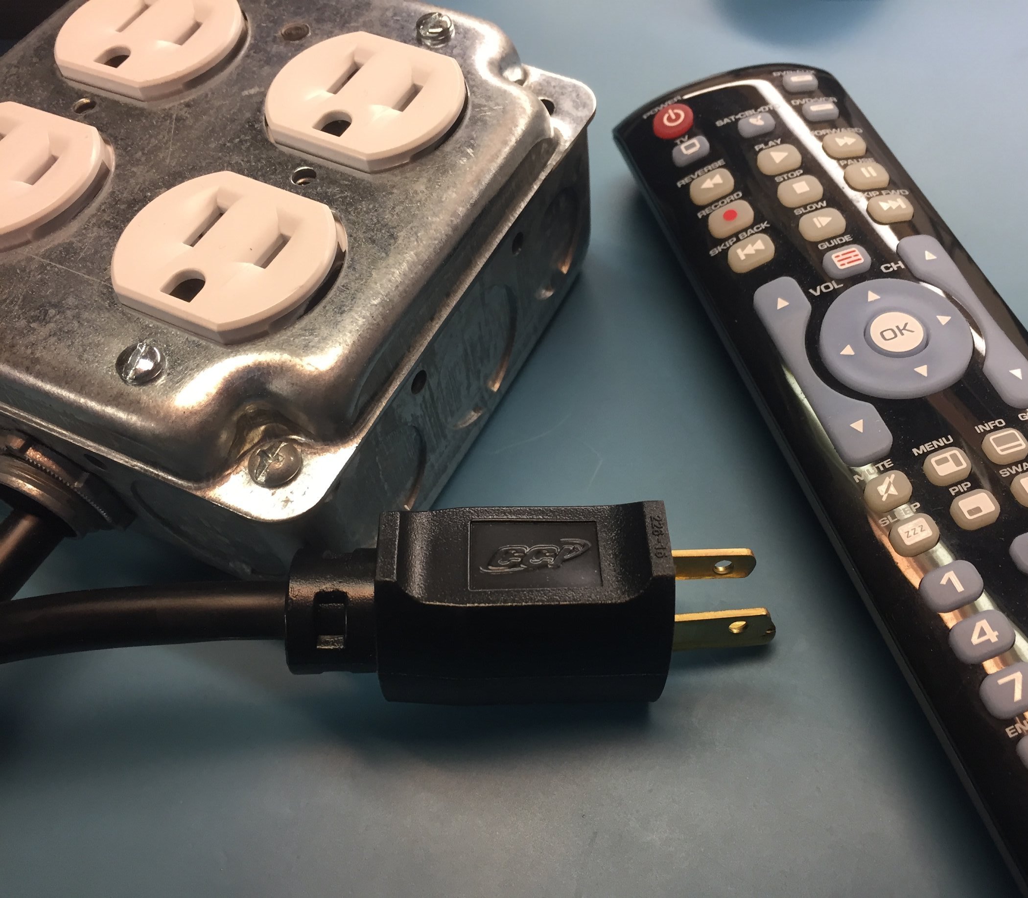 This project uses an ATmega328P microcontroller to receive inputs from an infrared (IR) receiver to control a set of four relays. The relays in this project are used to switch each of the outlets in a quad box on/off. This allows line-level devices to be remotely switched on or off with an infrared universal remote control.
Please be smart…
This project does have parts operating at line level voltages. Please be careful and pay close attention to what your doing once the project is powered. Getting poked can range from “hurt” to “dead” and the later is kinda permanent. Exercise sensible caution.The Hardware Progression
Many versions of the remote controlled outlet have been created. Some of which have been lost to the sands of time (and for the earlier revisions that’s not such a bad thing).
Hardware Version 0100
The first version of the hardware doesn’t really exist in any form any longer. It was nothing more than a prototype on a breadboard making use of an Arduino, an IR sensor, and a relay. For the electrical connection I had cannibalized an inexpensive extension cord picked up from the dollar store. This was a great way to test the project but was by no means safe if there are small children or idiots (I have friends that will touch just about anything they see) around as the bare wires carrying line level voltage were just poked into a breadboard which was sitting out in the open.
This setup was used to run the box fan in my apartment for several months before I finally upgraded to something a bit more safe. Truthfully, it was crafted from some spare bits I had laying around out of laziness. I sleep with a fan on 365 days a year for background noise at a minimum and I didn’t want to get back out of bed after getting cozy just to turn the fan on.
There was no real “hardware” for this version so I don’t even have so much as a schematic to offer up.
Hardware Version 0200
To replace the prototype version 0100 I crafted a PCB from scratch in my parents basement and assembled it into a 4” square electrical box. This version had four pigtails hanging out of it that was each controlled by a separate triac capable of dimming each of the channels. Admittedly, while this project had really good aspirations I got busy with college coursework and the project got shelved.
I never actually spent the time to debug this version. The idea was to have the ability to both switch devices on/off as well as to be able to dim resistive loads such as lamps. As it turns out I had some issues with the board layout and the triacs wouldn’t switch correctly and I also wasn’t satisfied with the 4A limit of the triacs so I threw in the towel and threw away the project.
I lost the hardware files for this version in a drive failure but I don’t really care too much as the design was flawed anyways.
Hardware Version 0300
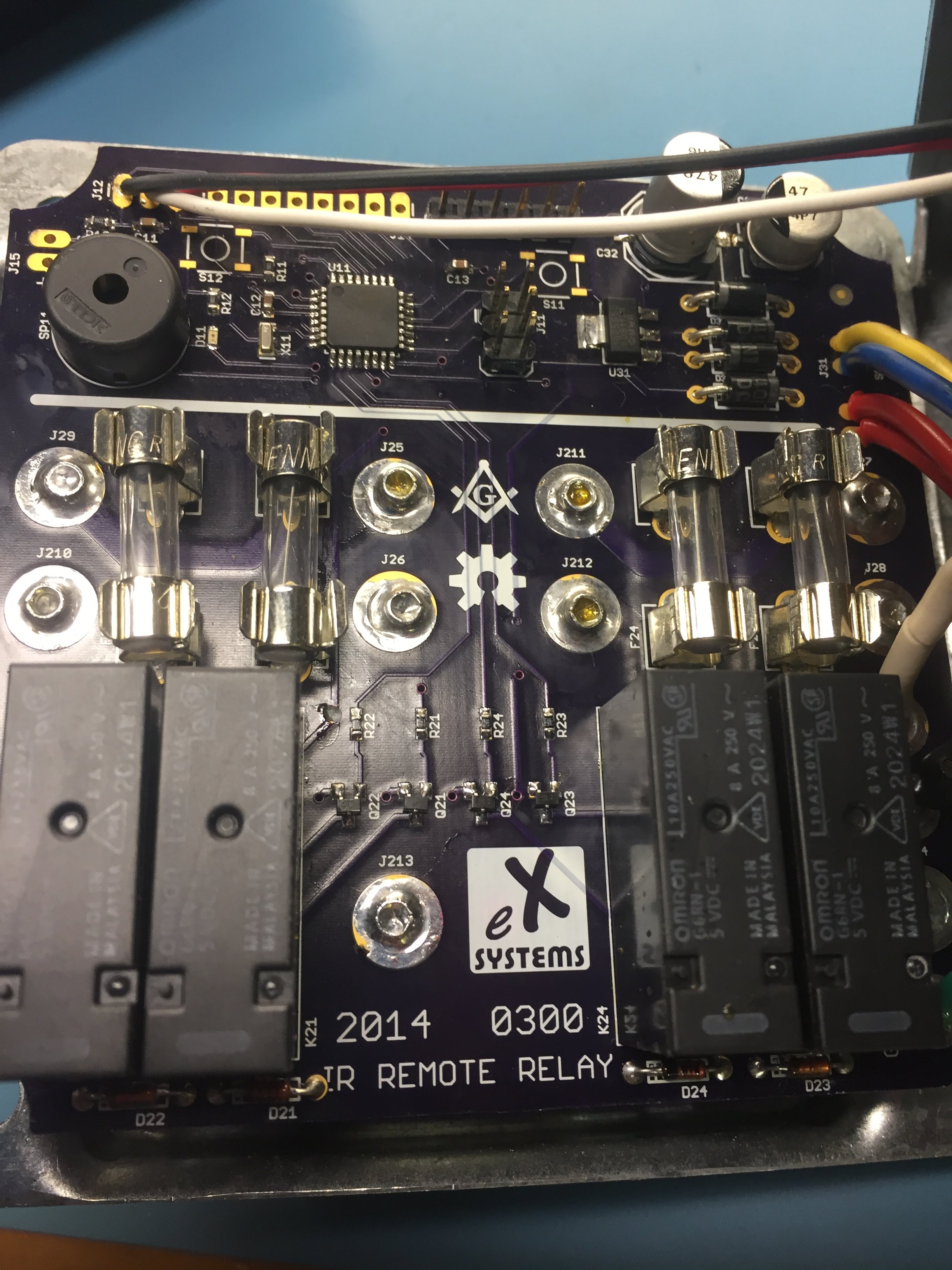
I decided to go back to the simpler relay approach for the next version of the hardware. This variant retained four channels but on a PCB that could be affixed directly to the back of the duplex receptacles in the enclosure. This made for a very compact setup and didn’t require the PCB to be mounted separately inside the enclosure.
I also opted to use IR receivers that were available from Monoprice for a steal of a deal. These receivers have a nicely packaged IR receiver at the end of a 5’ cable terminated in a standard 3.5mm “headphone” plug. I installed a corresponding jack in the side of the steel enclosure and worried not about what to do or where to mount the receiver. This is more convenient as the receiver can be placed anywhere such as on a shelf even when the electrical box gets buried behind an entertainment center, for example.
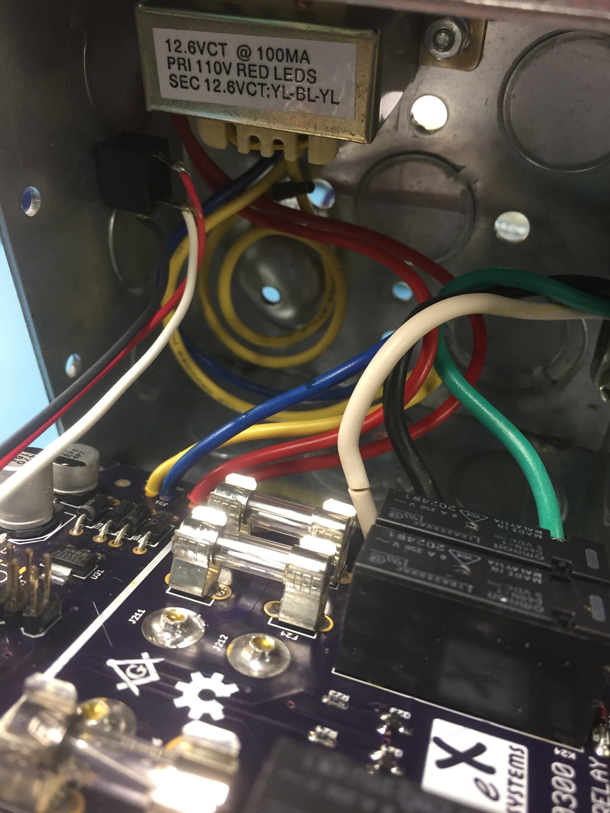
One of the major drawbacks of this version of the project was all of the external components. You can see in the picture that the 3.5mm jack was mounted off board as well as a modestly large (relative to the power consumption) transformer for the 5V power supply. This led to a considerable amount of work regarding the final assembly of the unit which I just felt was clunky.
- Remote Outlet 0301 Schematic
- Remote Outlet 0301 Eagle Files
- Remote Outlet 0301 Gerbers
- Remote Outlet 0301 BOM
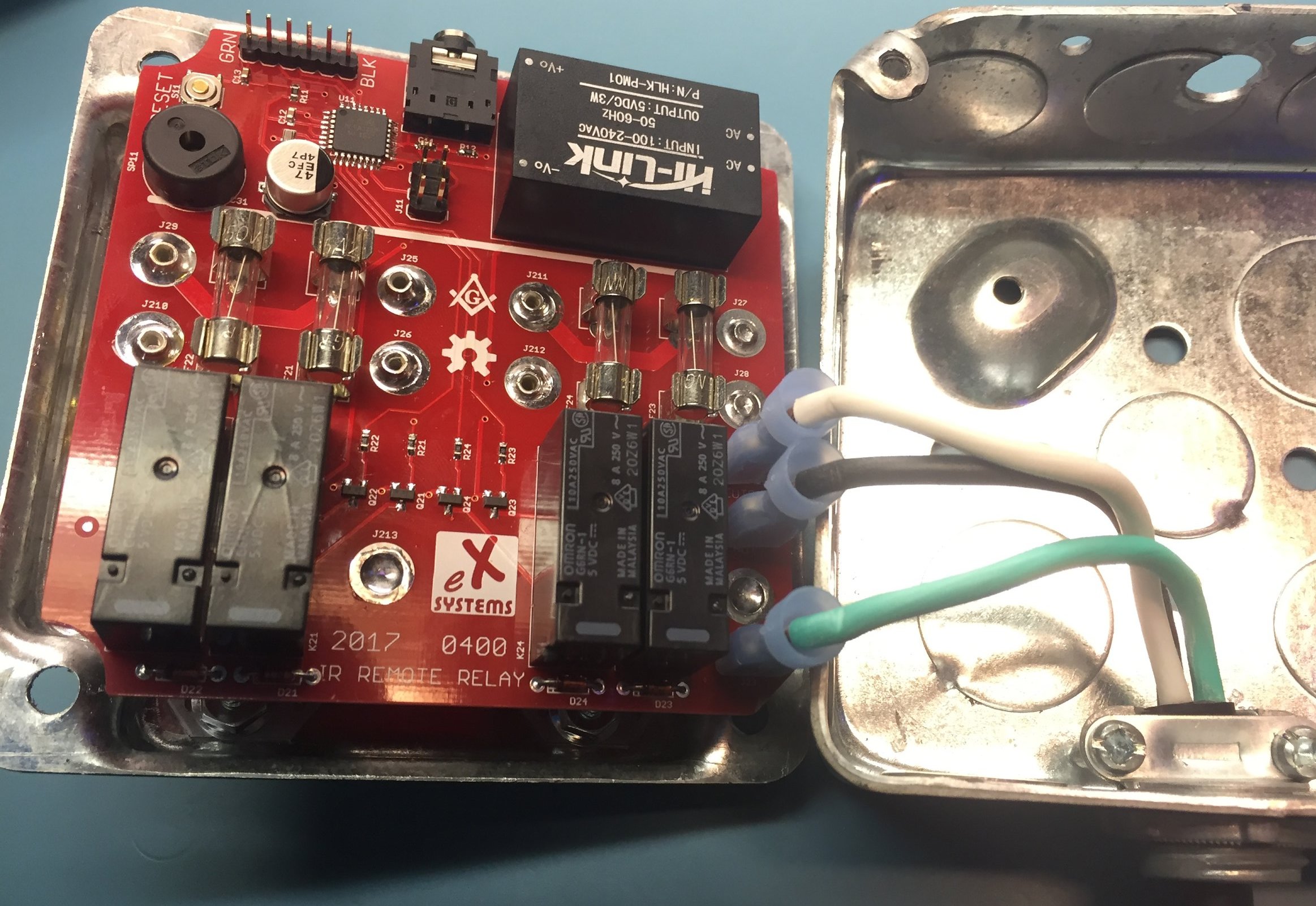
Hardware Version 0400
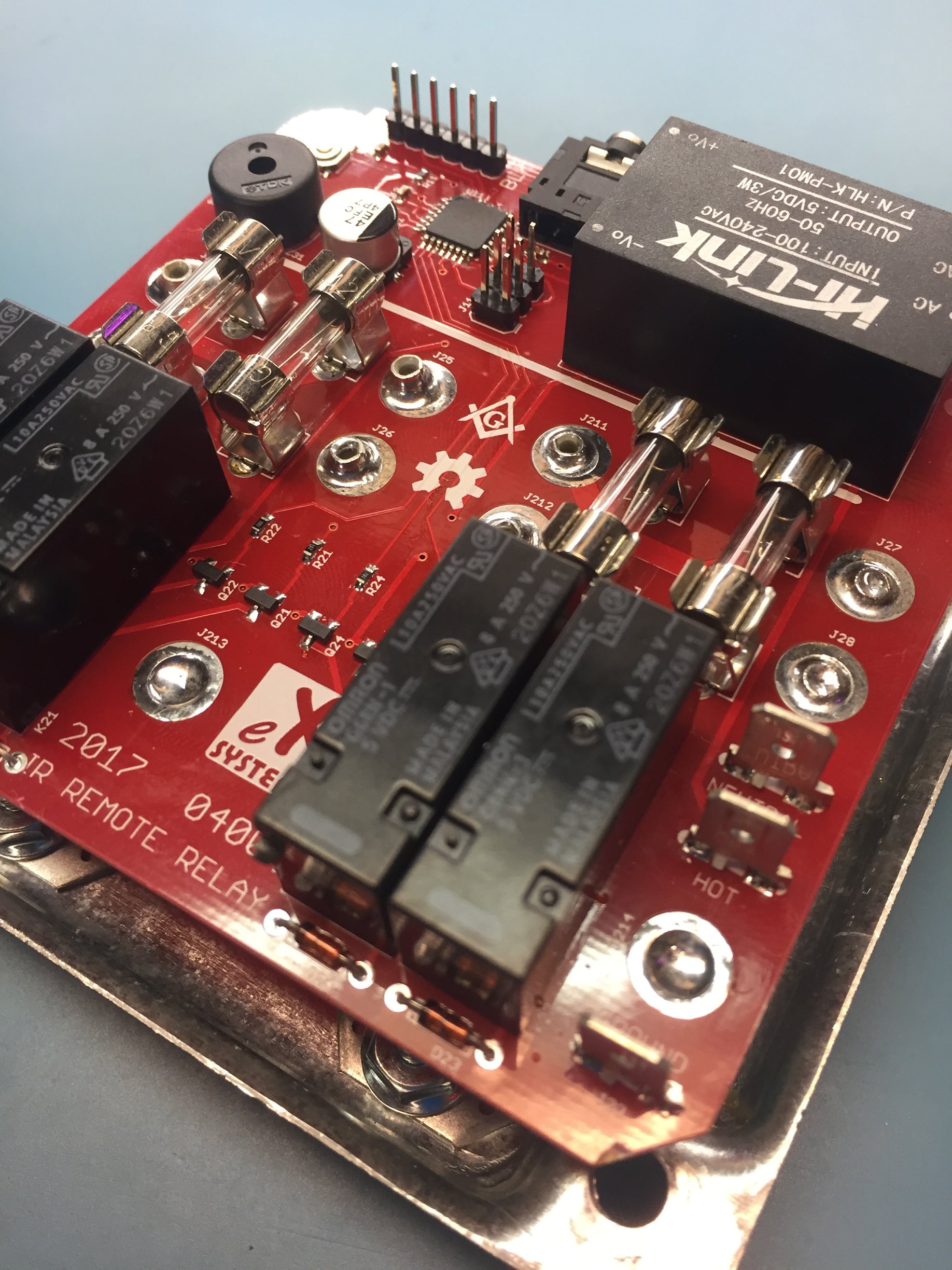
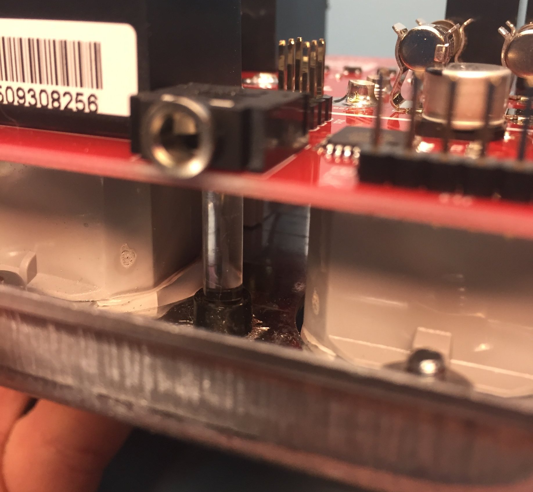
The latest incarnation of the remote outlet sees a change from a more traditional power supply that utilized a transformer, rectifier, and linear regulator in version 0300 to a switching power supply module that takes the 120V AC input and converts it down to isolated 5V output. This means that there’s no need for a clunky external transformer to be mounted in the box with the PCB.
This prompted me to also mount the 3.5mm jack to the PCB. The wire for the sensor can simply pass through an oversize hole in the enclosure to plug into the PCB. This reduced the external component count to zero and makes installation of the PCB into the enclosure a breeze.
I also swapped the soldered termination for the pigtail for blade disconnect terminals that allows the PCB to be easily installed and removed if necessary.
To recover board space the unused status and auxiliary headers were removed. They were put in on the earlier versions just in case they might be needed in some kind of adaptation of the project. Having never found such a use for them I have removed them in this version.
This version also sees a change to move the status LED to the “back” of the PCB which is really the top once installed. The intent is to allow for the installation of a light pipe located between the receptacles in the cover to show the status externally.
Besides the PCB, the project requires a two gang handy box, two 15 amp duplex receptacles, a pigtail with a male Edison connector on one end and bare wire on the other, and a Romex/NM clamp to mount the pigtail to the box.
- Remote Outlet 0400 Schematic
- Remote Outlet 0400 Eagle Files
- Remote Outlet 0400 Gerbers
- Remote Outlet 0400 BOM
Future Hardware Version 0500
No such version 0500 exists to date but if I were to change anything about this device I would replace the 3.5mm TRS headphone jack with a 3.5mm TRRS jack. I would then connect the second ring to the microcontroller and use it to detect when shorted to ground to know when the IR receiver is attached. The TRRS jack could then be used as either a serial port (TX and RX) or as a FSK port. The interface would allow reprogramming of the module as well as simple configuration of the defaults for the ports and the remote codes.
If you have an interest in such updates drop a comment below or feel free to take the version 0400 Eagle files from above and mod away. If you’re feeling generous and want to pay it forward on the open source hardware I would be happy to host updated versions here too.
Firmware
The firmware for the remote control outlet used Ken Shirriff’s IR Remote library to actualy parse the IR remote control commands. The logic for toggling the relays is very simple using nothing more than simple digitalWrite instructions.
The IR remote codes are hard coded in the firmware for this version which requires the user to first load and execute the IRDump example project from the IR remote library, connect a serial port, and use a console to dump the IR remote codes from button presses on the remote. The discovered codes can then be manually loaded back into the firmware file before uploading to the device.
I would like to eventually update the firmware to use EEPROM for storage of the codes and allow a simple interface to a PC or smartphone for setting or learning the codes. For now though, this does work.
Assembly
Step 1: Assemble the PCB
Assemble the PCB according to the schematic and BOM. You can refer to my soldering 101 tutorial for help. There’s nothing special to point out regarding the assembly of the board. Don’t forget about the status LED on the back side which you might want to tackle last so the board sits flat during soldering.
I always recommend double checking each of the pins on the IC to ensure that there are no shorts and use a multimeter to verify a reasonable amount of resistance between Vcc and GND. If the resistance is less than a few thousand ohms that generally means there’s a problem and powering the device will risk blowing up some parts and possibly releasing the magic smoke.
Step 2: Fabricate the box
The 2 gang handy box needs some hand modifications to accommodate the project besides running a pigtail through a clamp for the AC power input.
In the lid, between the receptacles one needs to drill an optional hole for a light pipe that gets mounted over the status LED on the PCB. To line this up I first mounted the receptacles with the terminals attached to the screws on the receptacles but not yet soldered to the PCB and measured distances from the LED to the edges of the cover. I then lined up as best as I could and drilled the hole. The result wasn’t perfect but it’s close enough to function properly.

In the box itself, a hole needs to be drilled for the 3.5mm connector to pass though for the IR receiver. The same general process applies as for the LED light pipe, measure and come as close as possible. This hole can be considerably over-sized to allow for some error in the placement. The only goal is to allow the connector to pass though the steel enclosure and plug into the jack on the PCB one mounted in the enclosure.
Step 3: Mount the PCB
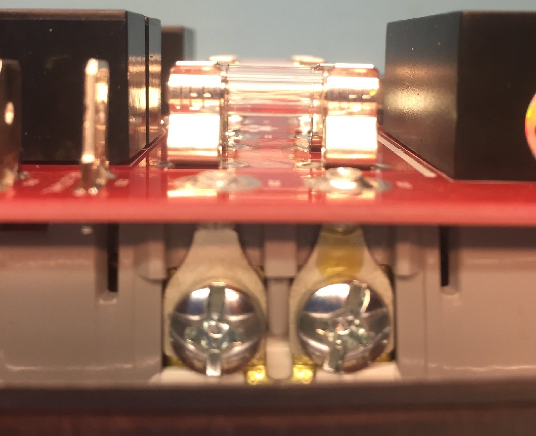
Start by mounting the receptacles in the cover if not already done. Next put a fork terminal on each screw of both outlets with the round end where the wire normally goes facing vertically out the back as squarely as possible. Next, place the assembled PCB over the receptacles. The terminals should pass through the 10 large holes on the PCB without much interference. Adjust as necessary.
Working through the terminals one at a time, solder the terminal to the PCB. This might require a hefty soldering iron as the terminals and PCB have quite a large thermal mass. Fortunately there isn’t much on the PCB to damage and the terminals are certainly safe. Be careful not to delaminate the PCB with a TON of heat and you should be already. In other words, feel free to use your dad’s 1000W soldering gun if you’d like.
Step 4: Setup Firmware
Crimp some spade terminals on the end of the wires from the pigtail, plug them into the PCB. Connect an AVR programmer, such as an AVR-ISP2, to the programming header and an FTDI breakout or cable to the FTDI header. Also, attach an IR sensor to the 3.5mm connector. Finally plug the pigtail into the wall to power the device. At this point don’t touch the PCB as there’s live voltage present on it.
Using the Arduino IDE select “Arduino Uno” from the board list and select your programmer from the menu. Use the “Burn Bootloader” option to flash a bootloader to the device and setup the proper fuses.
Load the IRRemote library’s IRDump example and upload to the device using the FTDI cable/breakout as you would typically do for any Arduino sketch. Open a serial monitor and configure the baud settings to match the example sketch. Point your remote at the sensor and press any button. You should see lots of data dumped to the terminal but the most important bit to note is the remote code for each of the four buttons you want to control a relay.
It is not important what device you configure the remote for (assuming that it’s a universal remote). You’ll probably want to make sure that the device you choose doesn’t actually control another device in the room though as the devices will both respond when the button is pressed.
Once you have all of the remote codes written down move on over to the firmware files above and update the remote control codes to match yours. Finally, flash the firmware to the device.
Unplug the pigtail before touching the board to unplug the programmer and FTDI cable.
Step 5: Button it up
Close up the cover and reattach the IR sensor through the hole in the box. Plug the device in and give it a test. Enjoy being able to control things from the sofa!
I realize that this is a fairly high level overview of the project and assembly steps so feel free to ask questions in the comment section below and I will be happy to clear things up for you.